

Table of Contents
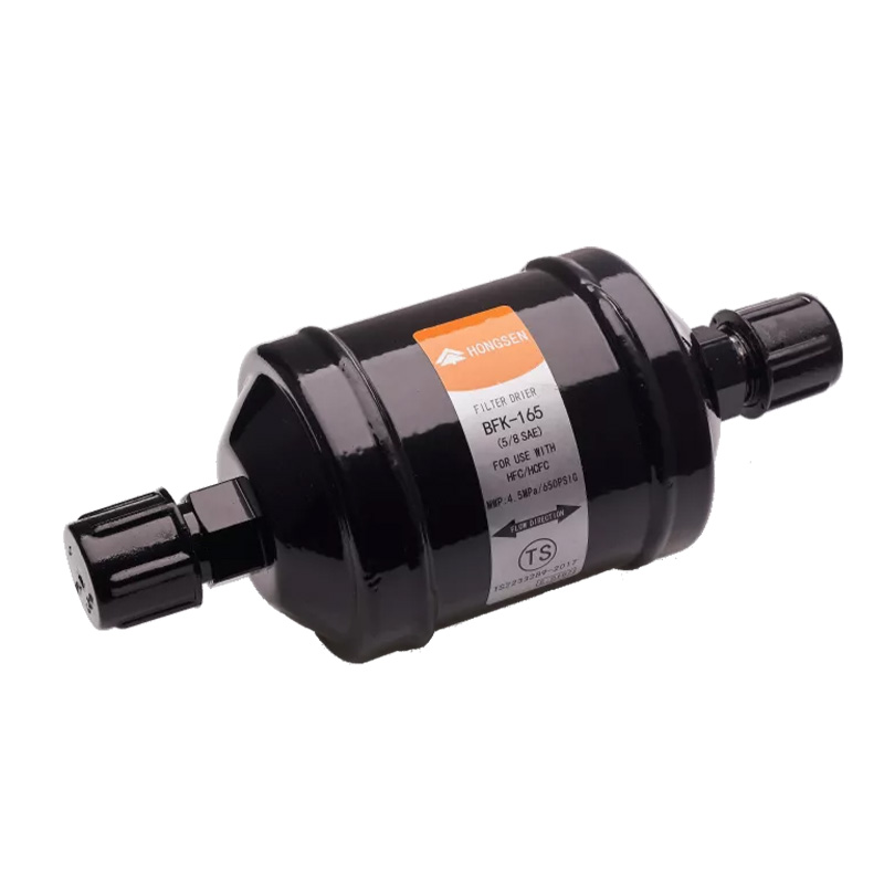
A reversing refrigeration circuit asks one liquid-line component to work in two directions. That is why a bi directional filter drier cannot be selected as though it were an ordinary one-way shell with an arrow printed on the label. The internal flow path, check-valve arrangement, desiccant core, and filtration sequence must protect the system in both operating modes.
This article explains how to select a bi directional filter drier for a heat-pump or other reversing circuit. It moves from circuit mapping to water capacity, refrigerant flow capacity, pressure drop, core chemistry, connections, placement, and replacement criteria.
The central procurement question is not “what pipe size is installed?” It is “what must the bi directional filter drier remove, and what mass flow must it pass, in each direction and at each design condition?”
Why a Reversing Circuit Needs a Purpose-Built Drier
A conventional liquid-line drier is normally optimized for one flow direction. Its internal support, filter media, and contaminant-retention arrangement may not work correctly when flow reverses. A bi directional filter drier uses an internal design intended to route refrigerant through drying and filtration media in either operating direction.
That distinction matters because captured debris should not be released when the cycle changes. The bi directional filter drier must also avoid creating an excessive liquid pressure drop in either mode, since reduced pressure at the metering device can cause flash gas and unstable evaporator feed.
Map the Two Operating Modes Before Reading a Catalog
Draw the refrigerant circuit twice: once in the first operating mode and once after reversal. Mark the active condenser, active evaporator, metering devices, check valves, receiver or accumulator, and liquid-line direction. Then locate the bi directional filter drier on both drawings.
For each mode, record refrigerant, mass flow or cooling duty, liquid temperature, upstream pressure, downstream pressure, and allowable pressure drop. The higher load is not automatically the controlling case. One direction may have lower liquid subcooling or less pressure margin before flashing.
- Trace flow from the active condenser outlet.
- Identify every check valve and bypass around the metering devices.
- Confirm that all liquid passes through the bi directional filter drier.
- Check whether any valve sequence can trap liquid between closed devices.
- Repeat the capacity and pressure-drop review for the reversed mode.
How the Internal Core and Flow Routing Work Together
A bi directional filter drier combines desiccant for moisture control with filter media for solid contaminants. Internal routing elements manage the direction change so refrigerant reaches the core correctly and previously captured material remains controlled. The exact construction is product-specific and should be verified rather than inferred from the shell shape.
The Rongyi BFK bi directional filter drier specifies a solid core made from 80% molecular sieve and 20% activated alumina, together with 100 μm filter cotton. Its published application includes HFC and HCFC refrigerants and synthetic POE or PAG oil systems. Compatibility still needs to be confirmed for the exact project fluid.
Standard, Bi-Directional, and Replaceable-Core Driers Compared
| Drier arrangement | Typical strength | Main selection caution |
|---|---|---|
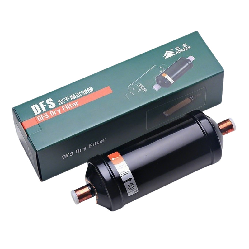
| Standard liquid-line drier | Simple one-way liquid-line protection | Do not assume retained debris and internal support are suitable for reverse flow |
| Bi directional filter drier | Drying and filtration through a reversing liquid circuit | Verify capacity and pressure drop in both operating modes |
| Replaceable-core shell | Serviceable capacity for larger systems or cleanup work | Confirm shell routing, core type, isolation, and maintenance procedure |
The comparison is about circuit function, not a universal ranking. A small permanently sealed system may favor a compact bi directional filter drier, while a larger installation may require a serviceable shell arrangement designed for reversal. The system designer must confirm the chosen architecture.
Water Capacity and Flow Capacity Solve Different Problems
Water capacity indicates how much moisture a drier can hold under stated test conditions. Refrigerant flow capacity indicates how much liquid can pass at a stated pressure drop and operating condition. A bi directional filter drier needs enough of both, but a high value in one category does not compensate for a shortfall in the other.
The AHRI 710 and 711 liquid-line drier page explains that standardized ratings address both water capacity and refrigerant flow capacity so products can be compared on a common basis. When using manufacturer data, check refrigerant, liquid temperature, evaporating condition, and the reference pressure drop behind the rating.
Select for the More Demanding Direction—Then Verify the Other One
Start with the operating mode that carries the greater refrigerant mass flow or has the smaller liquid pressure margin. Size the bi directional filter drier for that condition, then return to the second mode and confirm that flow is stable, pressure drop is acceptable, and internal routing still protects the circuit.
Avoid simply matching the bi directional filter drier connection to the reversing valve or liquid pipe. An oversized connection does not guarantee adequate drying capacity, and a large shell does not prove acceptable low-load behavior. Use the specific product selection data for the refrigerant and duty.
Match Desiccant Chemistry to Refrigerant and Lubricant
Desiccant must remove moisture without creating undesirable reactions with the refrigerant, lubricant, or additives. POE oils are hygroscopic, so controlling exposure during assembly and service is particularly important. The selected bi directional filter drier should be explicitly approved for the refrigerant-oil combination.
Do not assume that a drier suitable for one HFC is automatically suitable for every new blend or for another lubricant family. Use current product data and project requirements. The NIST refrigerant-property resources can support thermodynamic calculations, but material compatibility must come from the equipment and component documentation.
Connection Type Affects Both Installation and Future Service
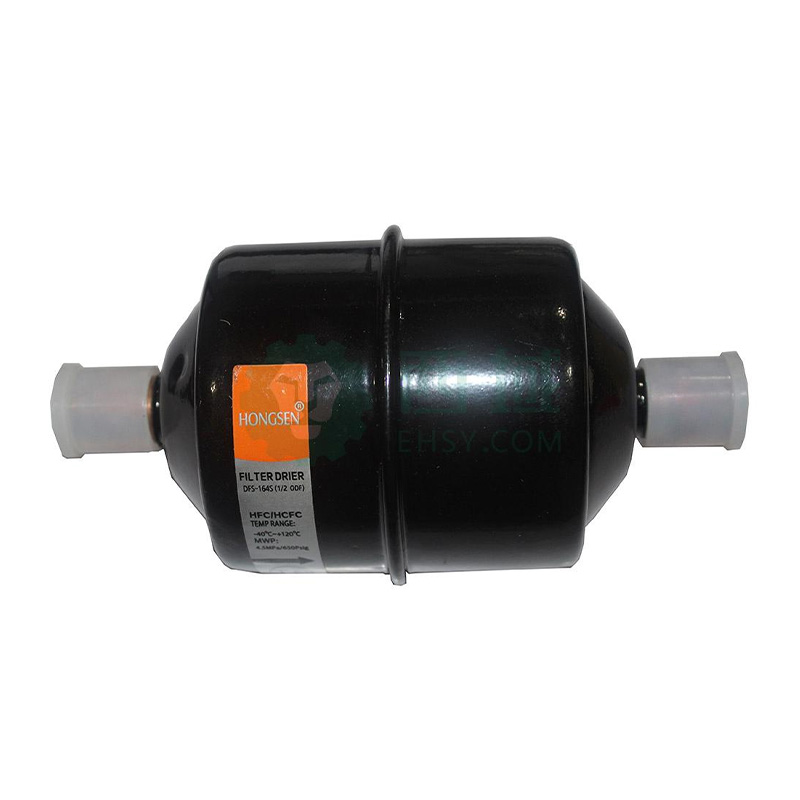
The BFK range includes threaded SAE and solder ODF connections in multiple sizes. Choose the connection standard used by the project, confirm actual tube outside diameter, and allow enough straight pipe for installation. A field adapter adds joints and can complicate replacement of the bi directional filter drier.
For soldered models, protect the core and internal seals from excessive heat according to the product instructions. Keep the drier sealed until it is ready to install because desiccant begins adsorbing moisture when exposed to ambient air. Support the piping independently so the bi directional filter drier is not used to correct misalignment.
Place the Drier Where Both Liquid Paths Actually Cross
A bi directional filter drier only protects flow that passes through it. Confirm that check valves, bypasses, and dual metering devices do not create a mode in which liquid avoids the drier. The location must also allow inspection, temperature measurement, leak testing, and replacement.
Coordinate placement with the reversing valve, thermostatic expansion valves, sight glasses, and service valves. If a moisture indicator is used, decide which direction and operating mode its location represents. A readable layout is easier to commission and far easier to troubleshoot later.
After the Circuit Has Been Opened, Control Exposure Time
A new bi directional filter drier should remain capped until pipe preparation is complete. During repair, keep open-line time short, use clean tools, prevent scale formation during joining, and evacuate with instruments and procedures suitable for the system. A drier cannot compensate for an uncontrolled assembly process.
Refrigerant recovery and circuit opening must follow local requirements. The EPA Section 608 equipment-management guidance covers U.S. stationary refrigeration service practices, and the OSHA lockout/tagout standard addresses the control of electrical, pressure, and other hazardous energy during maintenance.
Pressure Drop Is the Best Early Warning of a Loaded Drier
A bi directional filter drier may continue to look normal after its filter media loads with debris. Measure pressure or a meaningful temperature difference across the shell under a stable, known flow. Repeat the test in both operating modes when the circuit reverses.
A temperature difference can indicate pressure loss and flashing, but it must be interpreted carefully because ambient heat gain and changing load affect the reading. Trend the bi directional filter drier at comparable conditions. A growing differential is more persuasive than one isolated measurement.
Replace by Evidence, Not by Calendar Alone
Replacement is justified when the bi directional filter drier is restricted, has been exposed during major circuit work, is part of an approved cleanup procedure, shows external damage or leakage, or can no longer provide the required moisture protection. Follow the equipment maker’s procedure after a compressor failure or contamination event.
Do not repeatedly replace a bi directional filter drier without finding the moisture or debris source. Check leaks, evacuation practice, oil condition, tubing cleanliness, and whether the circuit was left open. The general refrigeration filter drier guide provides additional background on moisture, acids, and contamination.
Procurement Checklist for a Reversing Circuit
- Circuit diagram showing both refrigerant-flow directions.
- Exact refrigerant and lubricant.
- Cooling or heating duty in each mode.
- Liquid temperature and pressure available before each metering device.
- Allowable pressure drop through the bi directional filter drier.
- Required water capacity and the contamination history of the system.
- Connection type, actual tube OD, design pressure, and temperature range.
- Service access, installation orientation, and replacement procedure.
Providing these details lets the supplier evaluate the bi directional filter drier as a two-mode component. It also exposes whether another part of the circuit—not the drier—creates the limiting pressure drop or moisture risk.
Frequently Asked Questions
Can a standard filter drier be used in a reversing circuit?
Only if the specific system arrangement and component documentation explicitly allow it. A conventional one-way drier may not retain debris or route flow correctly after reversal. A purpose-built bi directional filter drier is designed for that duty.
Does a bi directional filter drier need an arrow?
The shell may show connection or flow information, but the defining feature is its approved internal operation in both directions. Follow the product markings and instructions; do not infer installation details from another drier family.
How is a bi directional filter drier sized?
Check water capacity and refrigerant flow capacity for the exact refrigerant and operating conditions in both modes. The controlling case may be the higher mass flow or the mode with the least pressure margin before the metering device.
When should the drier be replaced after a repair?
Follow the equipment and service procedure. Replacement is commonly considered after the sealed circuit has been opened, when restriction or moisture is indicated, or during an approved contamination-cleanup process. Diagnose the contamination source as well.
Can a moisture indicator replace pressure-drop checks?
No. A moisture indicator addresses dryness at its location; it does not show how much debris the filter has retained or the pressure loss through the bi directional filter drier. Use both moisture and flow evidence.
Select the Drier as a Two-Mode Component
A reliable bi directional filter drier selection connects three decisions: moisture capacity, contaminant retention, and acceptable liquid pressure drop in both directions. Mapping the circuit first prevents a one-way assumption from becoming a commissioning problem.
Review the BFK connection and model options alongside the two operating conditions. To request a selection review, send Rongyi Cold the refrigerant, lubricant, circuit diagram, capacity, liquid temperatures, pressures, and connection requirements. The ASHRAE Handbook portal offers broader refrigeration-system references.
