

Table of Contents
Shell and tube condenser cleaning should restore heat transfer or water flow without damaging tubes, tube sheets, heads, gaskets, or protective surfaces. The correct method depends on what is inside the tubes. Loose sediment, hard mineral scale, corrosion products, and biological deposits respond to different tools and chemicals, so cleaning begins with evidence rather than aggression.
A practical maintenance plan has five decisions: prove that fouling is significant, identify the deposit, isolate all energy and pressure, use a compatible removal method, and verify performance under comparable load. This shell and tube condenser cleaning workflow helps maintenance teams avoid unnecessary opening and creates records that improve the next service interval.
Prove Fouling With an Operating Baseline
High condensing pressure is not proof of dirty tubes. Low water flow, warm entering water, tower problems, air in the circuit, incorrect valves, refrigerant-side issues, and sensor error can produce a similar symptom. Before shell and tube condenser cleaning, record heat-rejection load, refrigerant condensing condition, entering and leaving water temperatures, water flow, and water-side pressure drop after operation stabilizes.
Compare those values with a clean baseline or the rated condition. A reduced water-temperature rise can mean lower load or reduced heat transfer; interpretation requires flow and load context. The water-cooled condensing unit guide helps separate system causes. Proceed with shell and tube condenser cleaning when the combined trend supports fouling or inspection is required by the shell and tube condenser cleaning plan.

Identify What Is Blocking Heat Transfer
Open an inspection point only after safe isolation, then examine representative tubes and collected material. Loose sand or rust may flush or brush out. Hard carbonate scale can adhere strongly. Slimy biological material, oily deposits, and corrosion products require different responses. Photograph the deposit and retain a sample if chemical identification is needed.
Water analysis can explain why the deposit formed. The USGS water-hardness resource describes calcium and magnesium contributions to hardness, but shell and tube condenser cleaning decisions may also require pH, alkalinity, chlorides, iron, biological activity, and treatment history. Correct the water-management cause or deposits will return after cleaning.
Create an Isolation Boundary Before Opening
A shutdown command is not an isolation boundary. Stop and lock out pumps, tower fans, compressors, heaters, and automatic valves that could energize or pressurize the equipment. Isolate the water side, drain it in a controlled manner, vent trapped pressure, and verify zero energy. Determine whether the refrigerant side must be isolated or recovered for the planned work.
Use site procedures and qualified personnel. The OSHA lockout/tagout standard covers hazardous-energy control, while EPA explains requirements relevant to refrigerant recovery, recycling, and reclaiming. Shell and tube condenser cleaning must also follow the equipment instructions, chemical safety data, local discharge rules, and the pressure-vessel safety plan.
Choose Mechanical Cleaning for Removable Deposits
Mechanical shell and tube condenser cleaning can use appropriately sized brushes, flexible shafts, low-risk scrapers, water flushing, or purpose-designed projectiles. The tool must match tube inside diameter, material, wall thickness, and deposit. A tool that is too hard or oversized can score the tube, thin protective layers, lodge inside a passage, or damage rolled joints.
Begin with the least aggressive effective method and keep tools aligned with the tube. Capture removed debris instead of pushing it into the water system. Count and inspect tubes as work progresses, noting blocked or damaged passages. Do not force a brush through an obstruction without understanding it. Mechanical shell and tube condenser cleaning should leave a traceable tube map, not just a pile of debris.
Use Chemical Descaling Only With a Controlled Procedure
Chemical shell and tube condenser cleaning may be appropriate for deposits that mechanical tools cannot remove efficiently, but the chemical must be compatible with tube, tube sheet, head, gaskets, coatings, and connected piping. Require a written procedure covering identification, concentration, inhibitor, temperature, circulation rate, exposure time, monitoring, neutralization, waste handling, and stop criteria.
Do not choose an acid solely because it dissolves a sample quickly. Rapid reaction can attack base metal or create gas and heat. The service provider should explain how metal loss is controlled and how completion is determined. Review water and chemical management within recognized references such as the ASHRAE Handbook. After shell and tube condenser cleaning, dispose of solution according to applicable environmental requirements.
| Deposit evidence | Possible method | Main risk to control | Verification |
|---|---|---|---|
| Loose sediment | Flush and compatible brushing | Driving debris deeper into the circuit | Clear discharge and restored pressure drop |
| Adherent mineral scale | Engineered mechanical or inhibited chemical process | Tube scoring or metal attack | Visual condition and thermal recovery |
| Biological film | Approved cleaning plus water-program correction | Exposure and rapid regrowth | Clean surface and follow-up water evidence |
| Corrosion products | Gentle removal followed by integrity assessment | Concealed wall loss | Tube inspection and leak test |
| Unknown mixed deposit | Sample identification before method selection | Incompatible or ineffective treatment | Documented deposit and acceptance result |
Inspect Every Part Exposed by Disassembly
Removal of a water head creates an opportunity to inspect gasket faces, bolts, partitions, sacrificial parts, coatings, tube sheets, rolled joints, and the ends of all tubes. Look for erosion patterns, pitting, dezincification where relevant, impingement, cracks, damaged threads, and evidence of refrigerant-to-water leakage. Shell and tube condenser cleaning is incomplete if the deposit is removed but an integrity problem is ignored.
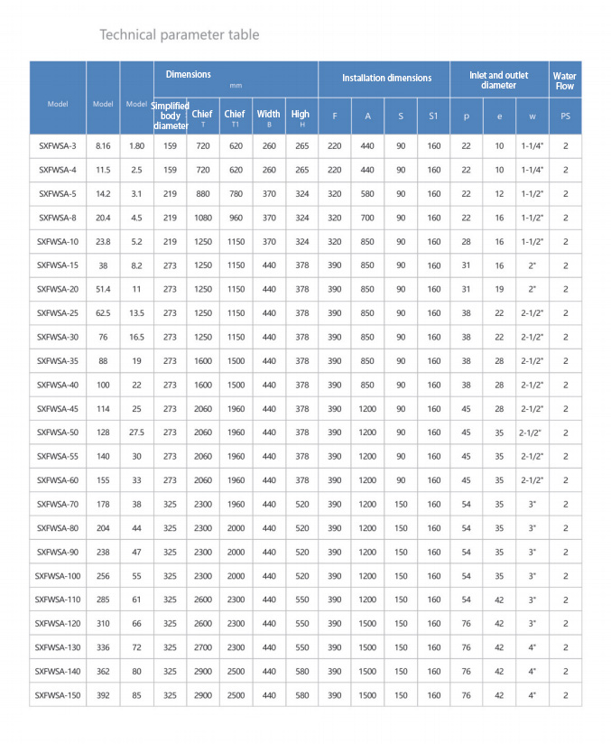
Replace specified gaskets rather than relying on a compressed seal of uncertain condition. Follow the model’s tightening pattern and torque procedure. The shell and tube water-cooled condenser page identifies the relevant product family; obtain model-specific service information before work. Pressure-boundary assessment should respect the applicable code basis, with ASME pressure-vessel information serving as one authoritative reference where relevant.

Reassemble, Vent, and Test in Stages
After shell and tube condenser cleaning, remove all tools and debris, confirm tube count, clean sealing surfaces, fit correct gaskets, and close the heads using the approved sequence. Refill the water side slowly, vent trapped air, inspect for leaks, and restore circulation before returning to full refrigeration load. Sudden pressurization can hide trapped air or shock weakened components.
Perform the required leak and pressure checks without exceeding equipment limits. If the refrigerant boundary was opened, follow the specified pressure test, evacuation, dehydration, and charging procedure. EPA’s refrigeration equipment-management guidance provides regulatory context. A shell and tube condenser cleaning record should state which boundaries were disturbed and which tests confirmed tightness.
Measure Whether Cleaning Restored Performance
Repeat the pre-cleaning readings at the closest practical load and operating condition. Compare entering and leaving water temperatures, flow, water-side pressure drop, condensing condition, and compressor operating evidence. A lower condensing temperature is meaningful only if water temperature, flow, and heat-rejection load are comparable.
Calculate or evaluate approach and heat transfer using a consistent method. Refrigerant saturation properties can be obtained from NIST REFPROP where engineering analysis is needed. If shell and tube condenser cleaning removes visible scale but performance remains poor, investigate flow measurement, tower capacity, refrigerant-side oil or non-condensables, tube damage, and the original selection.
Set the Next Interval From the Fouling Rate
Do not default automatically to the same calendar interval. Record deposit type and mass or severity, water chemistry, treatment changes, clean and fouled pressure drop, approach trend, operating hours, and cleaning method. These observations show how quickly the shell and tube condenser is losing performance and whether the water program is improving.
Use condition thresholds that the operations team can measure, supported by a maximum inspection interval appropriate to risk. If repeat shell and tube condenser cleaning is needed unusually soon, correct filtration, tower carryover, corrosion, biological control, makeup-water quality, or velocity rather than normalizing the problem. The compressor guide can help document the operating penalty associated with elevated condensing conditions.
Turn the Work Order Into a Repeatable Plan
A complete shell and tube condenser cleaning work order identifies equipment, deposit evidence, isolation points, cleaning method, compatible tools or chemistry, acceptance criteria, waste route, replacement parts, permits, readings, photographs, and responsible personnel. It also records tubes plugged or repaired and any integrity concern requiring engineering review.
For model-specific service access and replacement information, send the unit model, serial details, water analysis, operating trend, photographs, and previous shell and tube condenser cleaning history through the Rongyi Cold contact page. Good documentation lets the next shell and tube condenser cleaning begin with evidence instead of repeating the same exploratory work.
Frequently Asked Questions
Does high head pressure always mean dirty tubes?
No. Confirm load, entering-water temperature, flow, tower operation, valves, sensors, and refrigerant-side conditions before scheduling shell and tube condenser cleaning.
Should every deposit be acid cleaned?
No. The method must match the identified deposit and equipment materials. Uncontrolled chemical shell and tube condenser cleaning can damage tubes and seals.
Can the old head gasket be reused?
Follow the model instructions. Where replacement is specified, install the correct new gasket during shell and tube condenser cleaning and use the approved tightening procedure.
How is cleaning effectiveness verified?
Compare pressure drop and thermal performance at similar water temperatures, flow, and refrigeration load, and document visual condition after shell and tube condenser cleaning.
How often should the condenser be cleaned?
Base the interval on fouling rate, water evidence, operating trends, risk, and inspection history. Shell and tube condenser cleaning should not rely on an unsupported universal timetable.
