

Table of Contents
A shell and tube condenser transfers refrigeration heat into a circulating water stream through tubes contained within a pressure shell. It can provide stable heat rejection where suitable cooling water is available, but the design is only as dependable as its water assumptions. Entering temperature, flow, fouling, treatment, pump capability, and cleaning access all belong in the selection.
The central engineering question is whether the shell and tube condenser can reject the required heat at the project’s refrigerant condensing condition and worst credible entering-water condition. Answering it requires a thermal schedule, a hydraulic check, a pressure-boundary review, and an operating plan. This selection sequence keeps those disciplines connected.
Write a Two-Sided Design Schedule
Separate refrigerant-side and water-side inputs. For refrigerant, state fluid, total heat rejection, condensing condition, mass flow if known, inlet state, allowable pressure drop, connection arrangement, and design pressure. For water, state source, entering and leaving temperatures, design flow, allowable pressure drop, water quality, fouling basis, and minimum operating temperature.
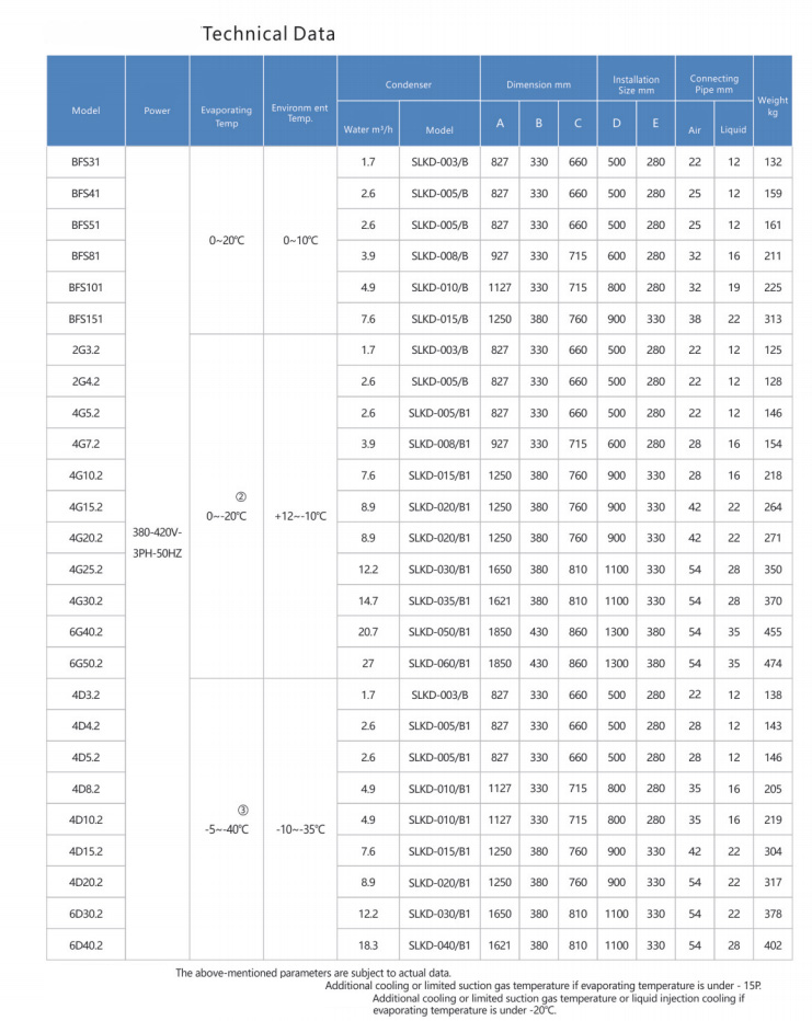
Avoid a request that gives only compressor horsepower or cold-room capacity. A shell and tube condenser must reject compressor heat as well as evaporator load. Use the condensing unit and evaporator matching guide to create a common operating point, and request project-specific data from the shell and tube water-cooled condenser product page.

Anchor Capacity to the Worst Entering-Water Condition
A cooling tower or closed loop does not deliver one constant temperature. Weather, tower approach, load, control settings, piping heat gain, and other users change the water reaching the shell and tube condenser. Select with the highest credible entering-water temperature during required full-load operation, not a convenient nominal value.
State the required leaving-water temperature or permitted rise as well. An unrealistically small rise demands unnecessary flow and pumping, while a large rise can reduce the average temperature difference and change capacity. The shell and tube condenser rating should show both water temperatures at the specified heat-rejection duty so the assumption can be checked during commissioning.
Derive Water Flow From the Energy Balance
Water flow follows from heat rejection and the planned temperature rise, subject to the fluid’s heat capacity. If glycol or another secondary fluid is used, its concentration changes heat capacity, viscosity, and pressure loss. Do not apply a water rating unchanged. Provide fluid composition and temperature so the shell and tube condenser can be rerated correctly.
Check the result against velocity limits for heat transfer, erosion, noise, and fouling. Too little flow can allow deposits and poor heat transfer; excessive velocity can raise pressure drop and threaten tube life. Use recognized engineering references such as the ASHRAE Handbook, then follow the selected shell and tube condenser documentation for permitted flow and velocity.
Add the Complete Water-Circuit Pressure Drop
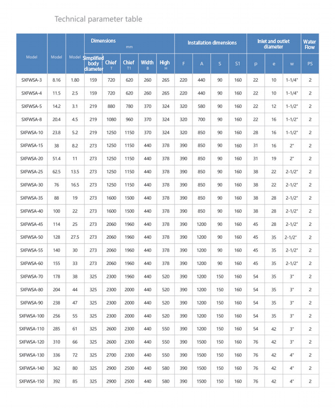
The pump must overcome more than the shell and tube condenser. Include supply and return piping, elevation effects where applicable, valves, strainers, tower distribution, control devices, fittings, and other heat exchangers. Evaluate the operating point on the pump curve rather than assuming nominal flow will appear at the equipment.
Ask for water-side pressure drop at the design fluid, temperature, and flow. Then check part-load control. A throttled valve may reduce flow below the minimum needed for stable heat transfer, while an oversized pump wastes energy and can create high velocity. The water-cooled condensing unit guide places shell and tube condenser hydraulics within the full refrigeration package.
Make Fouling an Explicit Design Variable
Deposits add thermal resistance and can narrow tube passages. Water source and treatment determine whether scale, sediment, corrosion products, or biological material is most likely. A fouling allowance is not permission to ignore water management; it is a declared design margin paired with monitoring and cleaning.
Obtain a water analysis and treatment plan appropriate to the system materials. The USGS explanation of water hardness describes how dissolved calcium and magnesium relate to hardness, but a complete program may need more parameters. Tell the supplier which fouling basis is used to rate the shell and tube condenser and how frequently inspection is expected.
| Design item | Required project value | Why it changes selection |
|---|---|---|
| Total heat rejection | Duty at one stated operating point | Sets thermal load, not room capacity alone |
| Entering and leaving water | Worst full-load inlet and planned rise | Defines available temperature driving force |
| Fluid and concentration | Water chemistry or glycol concentration | Changes properties, compatibility, and pressure drop |
| Allowable water pressure drop | Pump-system limit | Controls circuit and tube velocity choices |
| Fouling basis | Declared resistance and treatment plan | Protects capacity between cleanings |
| Refrigerant conditions | Fluid, condensing state, pressure limits | Controls shell duty, circuiting, and compliance |
| Service envelope | Head-removal and tube-cleaning space | Determines whether maintenance is physically possible |
Review the Refrigerant Pressure Boundary
Confirm the shell and tube condenser maximum allowable pressure, design temperature, refrigerant compatibility, relief provisions, connection sizes, internal volume, and applicable code basis. Refrigerant property calculations may use NIST REFPROP, while pressure-vessel requirements depend on jurisdiction and project specification. ASME BPVC Section VIII information is one authoritative reference, not a substitute for the local compliance review.
Discuss whether refrigerant condenses in the shell or tubes and how oil travels through the chosen configuration. Check pressure drop across the full load range, including unloaded operation. A shell and tube condenser can meet peak thermal duty yet create oil-management or control problems if the refrigerant circuit is poorly matched.
Reserve Space to Open and Clean It
Tube cleaning typically requires axial clearance to remove a head and pass tools through the tube bundle. Show that clearance on the plant-room layout, including doorways, columns, electrical panels, pumps, and future equipment. Also allow drainage, lifting, gasket replacement, inspection of tube sheets, and safe handling of water.
The shell and tube condenser should be isolated with serviceable valves and provided with suitable vents, drains, gauges, and measurement points. Equipment that fits the room but cannot be opened is not maintainable. Before disassembly, hazardous energy and pressure must be controlled according to site procedures; the OSHA lockout/tagout standard is a relevant safety reference.

Plan Controls for Tower and Part-Load Operation
Water temperature and flow controls interact with compressor head pressure. Tower fans, bypass valves, pump staging, and condenser-water valves should maintain stable operation without repeatedly crossing control thresholds. Low entering-water temperature can reduce condensing pressure enough to affect liquid delivery if controls do not compensate.
Define sensor locations and control authority. A temperature measured at the tower basin may not represent the shell and tube condenser inlet after mixing and piping heat gain. Check minimum flow, freeze risk, water-treatment needs, and shutdown sequencing. Coordinate the controls with the semi-hermetic piston compressor guide and the selected expansion device.
Compare Submittals on Equal Assumptions
Create a comparison sheet that fixes refrigerant, heat rejection, water temperatures, fluid, fouling allowance, and allowable pressure drop. Then compare rated capacity, water flow, pressure losses, design pressure, dimensions, weight, connection locations, service clearance, materials, and controls. If one shell and tube condenser appears much smaller, first check whether its rating assumptions are different.
For an application review, use the Rongyi Cold contact page and attach the two-sided schedule plus plant-room drawing. Ask the supplier to return the selected shell and tube condenser operating point and all deviations. This produces a reviewable shell and tube condenser decision rather than a model number detached from the project.
Frequently Asked Questions
Can cooling capacity be used as condenser duty?
No. The shell and tube condenser rejects evaporator load plus compressor heat. Calculate total heat rejection at the selected operating point.
Why is entering-water temperature so important?
It sets the available temperature difference for heat transfer. A warmer shell and tube condenser inlet generally reduces capacity at the same condensing condition.
Does a larger water flow always improve performance?
No. Flow must balance heat transfer, pressure drop, pumping energy, erosion risk, and permitted tube velocity for the shell and tube condenser.
What does fouling allowance mean?
It is a stated thermal resistance used in selection to account for expected deposits. A shell and tube condenser still needs water treatment, monitoring, and cleaning.
How much cleaning clearance is needed?
Use the model drawing and tool plan. Provide enough axial space to open the head and clean the full tube length of the shell and tube condenser safely.
