

Table of Contents
Compressor discharge temperature reflects the temperature entering compression, compression ratio, refrigerant properties, cooling method, and internal efficiency. A high compressor discharge temperature is a symptom with suction-side, high-side, application, electrical, and mechanical possibilities. Reducing the number without finding its source can conceal the operating risk.
The diagnostic method begins with a repeatable sensor location, then calculates suction superheat and compression ratio, verifies condenser performance, checks refrigerant and compressor envelope, and trends the full operating state. This avoids comparing unrelated readings taken at different distances from the compressor.
Standardize the Measurement Point
Discharge gas cools rapidly as it moves through piping and exchanges heat with ambient. Define sensor distance from the compressor, surface preparation, contact method, insulation, instrument, and stabilization time. Compressor discharge temperature values are comparable only when this method remains consistent.
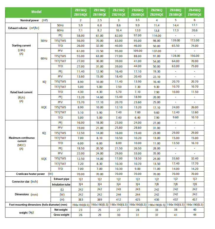
Record shell temperature separately and do not substitute an infrared reading on reflective copper without accounting for emissivity and spot size. Follow the compressor manufacturer’s approved limit and measurement location. Verify the contact sensor against a suitable reference and inspect whether insulation is tight enough to reduce ambient influence. Photograph the location and mark it for future rounds. A value measured near a discharge muffler, service valve, or uninsulated bend may differ materially from one taken at the required straight-pipe location. The semi-enclosed piston compressor page identifies the product family, but model data govern acceptance. Standardizing this method makes compressor discharge temperature a usable trend instead of a collection of unrelated numbers.

Find How Hot the Suction Gas Enters
Measure suction pressure and temperature at the compressor and calculate superheat. Evaporator superheat plus suction-line heat gain determines the inlet condition. Excessive inlet temperature directly raises compressor discharge temperature even when condensing pressure is ordinary.
Inspect expansion-valve feed, evaporator airflow and frost, insulation, long hot suction runs, and low load. Use the expansion valve guide and pressure reading guide. Correct the source of excess superheat rather than adding unapproved cooling.
Calculate the Pressure Ratio at the Same Instant
Compression ratio depends on absolute suction and discharge pressures. Low suction, high condensing pressure, or both increase the work and heat of compression. Record simultaneous values and convert correctly. Compressor discharge temperature diagnosis is incomplete when only the high-side gauge is considered.
Use NIST REFPROP for refrigerant properties where engineering calculations are needed. Compare the operating point with the approved compressor envelope and note capacity stage. A ratio acceptable at one suction temperature may not be acceptable at another application.
Audit Heat Rejection Before Blaming the Compressor
Check condenser entering air or water, fan or pump operation, coil or tube cleanliness, hot-air recirculation, valves, head-pressure controls, and ambient. Poor heat rejection raises discharge pressure and compressor discharge temperature. Restore the designed airflow or water flow before interpreting charge or internal condition.
The condenser coil cleaning guide and air-cooled condenser guide provide relevant checks. If high pressure persists, evaluate non-condensables, overcharge, receiver condition, and refrigerant circuiting with qualified procedures.
Confirm Refrigerant, Oil, and Application Envelope
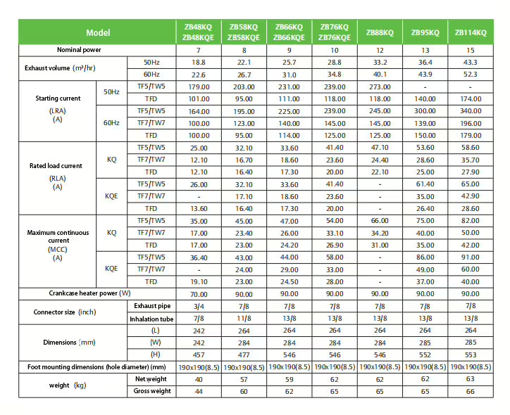
The compressor must be approved for the refrigerant, oil, evaporating range, condensing range, return-gas condition, and cooling accessories. A retrofit refrigerant can change mass flow and discharge behavior. Compressor discharge temperature limits must come from the exact model and approved application, not another compressor using the same pipe size.
Verify any liquid or vapor injection, external cooling, unloading, and control logic against documentation. Do not improvise injection to lower compressor discharge temperature. Incorrect liquid delivery can damage the compressor or dilute oil.
| Measurement pattern | Likely direction | Evidence to add |
|---|---|---|
| High suction superheat, normal head | Evaporator feed or suction heat gain | Valve, airflow, line insulation, load |
| Normal suction condition, high head | Heat-rejection problem | Fans/water, fouling, recirculation, ambient |
| Low suction and high head | High compression ratio on both sides | Feed/load plus condenser evidence |
| Temperature rises after repeated starts | Cycling or protection problem | Start count, run time, voltage, current |
| High temperature with abnormal sound/current | Possible internal condition | System causes corrected, specialist assessment |
Check Electrical and Cycling Contributions
Measure voltage, phase condition where applicable, current, terminal heat, contactor condition, and protection history. Repeated starts and short runs add motor heat and prevent stable oil and refrigerant conditions. Compressor discharge temperature should be trended with current and cycle state, not only pressures.
Never bypass temperature or motor protection. Apply energy isolation under the OSHA lockout/tagout standard. Use the compressor guide to coordinate electrical evidence with refrigeration conditions.
Trend the Operating Envelope Instead of One Peak
Log suction and discharge pressures, suction temperature, compressor discharge temperature, ambient or water conditions, fan stages, current, load, valve state, and time. Include pull-down, stable load, unloading, defrost recovery, and the event that produced the alarm. A single peak without context cannot show which variable led. Plot the variables on one timeline so changes in superheat, head pressure, current, and control stages can be compared before the temperature rises. Note sensor sampling intervals because a slow logger may miss a short control event. If one compressor in a parallel rack behaves differently, compare matched machines at the same suction and discharge conditions. This differential comparison can reveal an application or internal concern that a system-wide average hides, while still avoiding a premature compressor diagnosis.
Establish warning and action thresholds from equipment documentation and control strategy. Trend rate of rise as well as final value. A slowly worsening pattern can reveal fouling or feed deterioration before protection trips. Record how alarms latch, reset, and notify operators. If the sensor is also used for protection, verify its controller scaling and fault response separately from the portable service measurement. Do not move the installed sensor merely to make the displayed trend agree with another location.
Verify the Cause-Specific Repair
Repeat the same measurement method under a comparable operating point after correction. Confirm suction superheat, pressure ratio, heat rejection, electrical values, and protection status along with compressor discharge temperature. Retain compressor discharge temperature limits and alarm delays in the service record. If the value remains abnormal after system causes are corrected, stop and obtain model-specific technical assessment.
Refrigerant service must follow qualified procedures and applicable EPA guidance. The ASHRAE Handbook provides system fundamentals. Send the model, refrigerant, oil, sensor method, synchronized trend, and service history through the contact page for compressor discharge temperature review.

Frequently Asked Questions
Where should discharge temperature be measured?
Use the model-approved location and a repeatable insulated contact method. Compressor discharge temperature changes quickly along the pipe.
Can high superheat raise discharge temperature?
Yes. Hot suction gas enters compression at a higher temperature and can raise compressor discharge temperature.
Why use absolute pressure for compression ratio?
Compression ratio is based on absolute pressures; using gauge pressure directly distorts compressor discharge temperature analysis.
Can a dirty condenser cause high discharge temperature?
Yes. Poor heat rejection raises condensing pressure and can increase compressor discharge temperature.
What proves a repair worked?
Comparable measurements showing acceptable superheat, pressure ratio, heat rejection, electrical state, and compressor discharge temperature prove the correction.
